

During the current wave of global industrialization, various overseas industrial parks and manufacturing zones are experiencing a massive surge in construction. These modern parks are densely packed with factories spanning multiple sectors—such as mechanical processing, textile manufacturing, hardware stamping, food production, and plastics injection molding. The daily operations of these facilities rely heavily on a massive volume of inductive loads, including power motors, water pumps, ventilation fans, and full-scale factory production lines.
However, once the park's overall power distribution system goes live, facility managers and enterprise owners frequently encounter a shared, thorny financial headache: skyrocketing electricity bills accompanied by severe low power factor penalties. To guarantee the stability of the public power grid and optimize overall energy expenditures, the Low-Voltage Intelligent PFC (Power Factor Correction) Reactive Power Compensation Cabinet has become an indispensable, standard electrical solution in modern industrial power distribution rooms. Acting as an invisible "power balancer" behind the scenes, it continuously cuts operational costs and enhances power quality across the entire facility.
Why Do Modern Industrial Power Distribution Systems Require Reactive Power Compensation?
In an AC electrical grid, the vast majority of inductive loads within an industrial park absorb electrical energy that is fundamentally split into two distinct components:
Active Power: The actual electrical energy converted into mechanical energy, heat, or light to drive equipment and perform useful work.
Reactive Power: The non-working electrical energy required exclusively to establish and maintain the alternating magnetic fields that allow motors and other inductive equipment to function properly.Although reactive power does not perform direct work, it occupies valuable capacity in transmission lines and main transformers. When the collective reactive power demand of an industrial park escalates, the system's Power Factor (PF)—the ratio of active power to total apparent power—drops significantly.
The Risks of a Low Power Factor to Industrial Parks:
Power Factor Penalties: Utility companies typically require a power factor of $0.9$ or $0.95$ and above. Failing to meet this threshold triggers heavy monthly penalty surcharges.
Line and Transformer Overloading: Excessive reactive current causes severe cable heating, accelerates insulation aging, and wastes transformer capacity.
Degraded Voltage Quality: Uncontrolled reactive currents cause severe voltage drops and line-end flicker, disrupting precision machinery.
This is precisely where the low-voltage PFC reactive power compensation cabinet comes into play. It utilizes capacitive reactive current to directly counteract the inductive reactive current produced on-site. Through this electrical "cancellation effect," reactive current is contained locally, significantly relieving the supply burden on the external public utility grid.
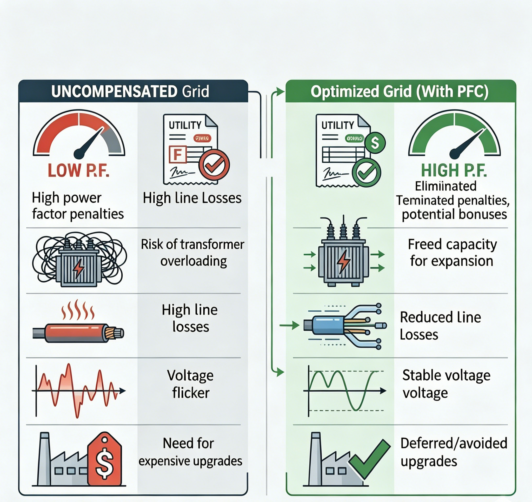
Core Differences:
Before vs. After Implementing PFC Compensation Cabinets
Metric |
Uncompensated Grid (Raw Status) |
Optimized Grid (With PFC) |
Utility Bill |
Heavy low power factor penalties. |
Penalties eliminated (≥ 0.95); potential bonuses. |
Transformer Headroom |
High reactive load risks system overloading. |
Frees up capacity for future facility expansion. |
Internal Line Losses |
High current causes cable heating & heavy loss. |
Lower current reduces line losses and cable aging. |
Voltage Stability |
Large voltage drops & flicker during machine starts. |
Stabilizes end-of-line voltage; reliable power. |
Expansion Investment |
Requires expensive upgrades to main transformers. |
Maximizes current efficiency; defers or avoids upgrades. |
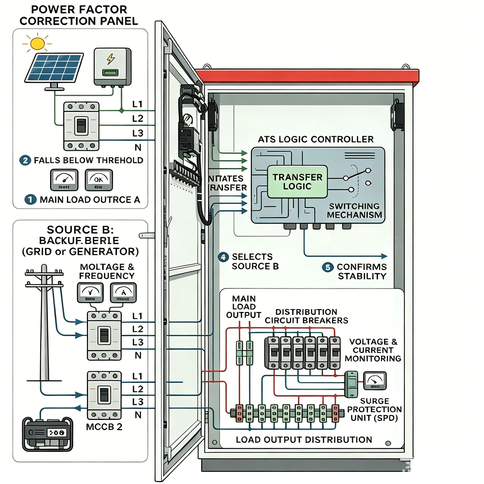
System Architecture and Operational Mechanism of Intelligent PFC Cabinets
A well-engineered low-voltage PFC capacitor compensation cabinet is systematically assembled from several core electrical components:
Intelligent PFC Controller: The system "brain" that monitors grid signals in real time and automatically issues dynamic switching commands.
Protective Circuit Breakers & Fuses: Provide incoming isolation along with overload and short-circuit protection for main and branch circuits.
Switching Components (Contactors/Thyristors): The executors that frequently connect or disconnect capacitor banks based on controller instructions.
Power Capacitor Banks: The primary source of compensation, providing capacitive current to balance out inductive loads.
Series Tuning Reactors: Optional components used to suppress high-frequency harmonics and prevent capacitor resonance damage.
In actual industrial environments, production loads fluctuate constantly. When heavy machinery starts up, the controller detects a drop in the power factor and immediately switches "in" the appropriate capacity of capacitor banks. Conversely, when equipment shuts down, the system rapidly switches them "out" to prevent over-compensation and reactive power feedback into the utility grid. This dynamic closed-loop control keeps overall energy efficiency at an optimal level.
FAQ
Q1: What makes PFC "intelligent" compared to traditional manual systems?
A1: Traditional fixed capacitors cannot adapt to changing loads, causing over-compensation at night and under-compensation during peak hours. Intelligent PFC uses microcomputers to automatically monitor grid loads, executing dynamic, on-demand switching and step rotation to ensure even capacitor wear.
Q2: Should an industrial PFC cabinet use Contactors or Thyristors for switching?
A2: For stable, slow-changing loads (e.g., textiles, food processing), specialized capacitor contactors are highly cost-effective. For rapidly fluctuating loads with heavy shock currents (e.g., injection molding, stamping, welding), thyristor switches are essential due to their millisecond response and zero-crossing, sparkless switching.
Q3: How is "harmonic interference" resolved in capacitor compensation?
A3: Non-linear loads like frequency inverters inject high-frequency harmonics into the grid, which can cause standard capacitors to overheat or bulge due to resonance. To resolve this, series tuning reactors must be added to build an anti-harmonic PFC cabinet that blocks and suppresses harmonics.
Q4: Does implementing a PFC cabinet reduce the active energy consumption of factory machinery?
A4: No, it does not slow down the main active meter or change the active power required to do actual work. Its financial savings come entirely from eliminating power factor penalties, drastically reducing internal cable heat losses, and maximizing transformer capacity.
Q5: What are the critical maintenance steps for an industrial PFC cabinet?
A5: Maintenance focuses on four key areas: keeping cabinet ventilation clear (capacitors are heat-sensitive); checking for capacitor bulging or leaks; periodically de-energizing the cabinet to tighten wiring terminals (preventing fire risks); and measuring branch currents with a clamp meter to replace degraded units early.
Conclusion
In an era focused on green, low-carbon initiatives and lean operations, low-voltage intelligent PFC reactive power compensation cabinets are no longer just optional electrical accessories. They represent a core strategic asset for overseas industrial parks and modern production zones to achieve grid-level cost reduction, maximize energy efficiency, and stabilize power quality. By scientifically configuring these systems, industrial hubs can completely eliminate expensive utility penalties while significantly extending the service life of their distribution assets, building a robust and sustainable electrical foundation for global industrial modernization.
Table of Contents
- Why Do Modern Industrial Power Distribution Systems Require Reactive Power Compensation?
- Core Differences:
- System Architecture and Operational Mechanism of Intelligent PFC Cabinets
-
FAQ
- Q1: What makes PFC "intelligent" compared to traditional manual systems?
- Q2: Should an industrial PFC cabinet use Contactors or Thyristors for switching?
- Q3: How is "harmonic interference" resolved in capacitor compensation?
- Q4: Does implementing a PFC cabinet reduce the active energy consumption of factory machinery?
- Q5: What are the critical maintenance steps for an industrial PFC cabinet?
- Conclusion