

Essential Guidelines for Solar Combiner Cabinet Sizing in Utility-Scale Applications
The success of a 1.5 MW utility solar farm heavily depends on properly sized solar combiner cabinets. These critical components serve as the central collection points for multiple photovoltaic strings, making their correct specification vital for system performance and safety. When sizing a solar combiner cabinet, engineers must carefully consider various technical parameters including maximum system voltage, short circuit current ratings, and environmental factors that influence the installation.
A well-designed solar combiner cabinet not only ensures optimal power collection but also provides essential protection features that safeguard your investment. This comprehensive guide will walk you through the crucial aspects of sizing combiners for utility-scale installations, helping you avoid common pitfalls while maximizing system efficiency.
Understanding Solar Combiner Cabinet Components and Specifications
Core Components of a Solar Combiner Cabinet
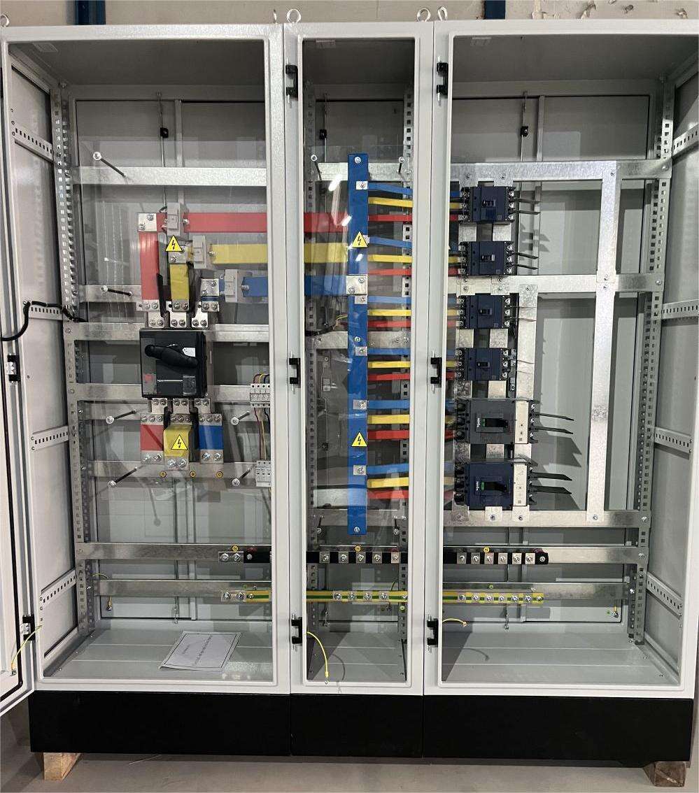
The solar combiner cabinet houses several essential components that work together to efficiently collect and protect PV string circuits. The main busbar serves as the power collection point, while fuses provide overcurrent protection for individual strings. Additional components include surge protection devices, disconnecting means, and monitoring equipment when specified.
Cabinet enclosure ratings must match the installation environment, typically requiring NEMA 4X or better for outdoor installations. The internal layout must facilitate proper heat dissipation and provide adequate working space for maintenance personnel.
Technical Specifications and Rating Requirements
When selecting a solar combiner cabinet, several critical ratings must be evaluated. The maximum system voltage rating must exceed the highest open-circuit voltage possible in the system, including temperature-related voltage increases. Current ratings for busbars and terminals must accommodate 125% of the maximum continuous current per NEC requirements.
Voltage drop calculations across the combiner cabinet components should be performed to ensure system efficiency. Generally, the total voltage drop from string inputs to the combiner output should not exceed 1% under full load conditions.
Calculating Fuse Ratings and Protection Requirements
String Fuse Sizing Methodology
Proper fuse sizing begins with calculating the maximum series fuse rating (MSFR) of the solar modules being used. The selected fuse must protect against reverse current while allowing normal operating current to flow unimpeded. Typically, fuses are sized at 1.56 times the module's short circuit current (Isc) to account for environmental factors.
Temperature derating must be considered when selecting fuses, as their current-carrying capacity decreases at higher temperatures. For utility-scale installations, fuse selection should account for the highest expected ambient temperature plus the temperature rise within the cabinet.
Overcurrent Protection Coordination
Protection coordination ensures that fuses operate in the correct sequence during fault conditions. The main output circuit protection must be properly coordinated with string fuses to maintain selectivity. This prevents nuisance tripping and helps isolate faults to the smallest possible section of the array.
Modern solar combiner cabinets often incorporate advanced monitoring features that can alert operators to approaching overcurrent conditions before fuse operation becomes necessary. This predictive capability helps maintain system uptime and reduce maintenance costs.
Bus Ampacity and Conductor Sizing Guidelines
Main Bus Ampacity Requirements
The main bus must be sized to handle the combined current from all connected strings with appropriate safety margins. NEC requirements specify that continuous current shall not exceed 80% of the bus rating. For a 1.5 MW installation, careful attention must be paid to current distribution and heat dissipation within the cabinet.
Bus material selection impacts both current-carrying capacity and cost. While copper offers superior conductivity, aluminum buses with appropriate plating can provide a cost-effective solution when properly sized for the application.
Terminal and Conductor Considerations
Terminal selection must account for both electrical and mechanical requirements. Terminals must be rated for the maximum system voltage and sized to accommodate the selected conductor size. Mechanical strength is particularly important in outdoor installations where thermal cycling can stress connections.
Conductor sizing within the solar combiner cabinet must account for ampacity derating due to ambient temperature and conduit fill. All conductors should be selected based on 125% of the maximum continuous current they will carry.
Voltage Drop Analysis and System Efficiency
Calculating Total Voltage Drop
Voltage drop through the solar combiner cabinet impacts overall system efficiency and must be carefully managed. The total voltage drop from string inputs to combiner output should be calculated considering all connection points and conductors. Each connection point typically contributes 0.1 to 0.2 volts of drop under full load.
Advanced modeling software can help predict voltage drop under various operating conditions, allowing designers to optimize component selection and layout for maximum efficiency.
Efficiency Optimization Techniques
Several techniques can be employed to minimize voltage drop and improve system efficiency. Using larger conductors than minimally required, implementing parallel bus arrangements, and optimizing conductor routing can all contribute to reduced losses. The additional material cost is often justified by improved system performance over the installation's lifetime.
Regular thermal imaging and connection resistance testing help maintain optimal efficiency by identifying developing issues before they significantly impact performance.
Environmental and Installation Considerations
Temperature Management Strategies
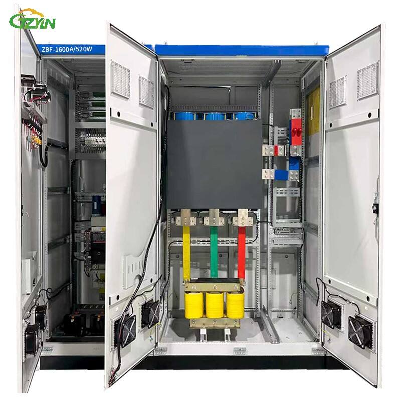
Effective temperature management is crucial for solar combiner cabinet longevity and performance. Cabinet ventilation must be designed to maintain internal temperatures within acceptable limits for all components. This may require the use of vents, fans, or climate control systems depending on the installation location.
Temperature monitoring systems can provide early warning of cooling system issues or unexpected heat buildup, allowing preventive maintenance to be performed before component damage occurs.
Physical Installation Requirements
Cabinet mounting location must consider accessibility for maintenance, protection from physical damage, and optimal cable routing. Adequate working clearances must be maintained around the cabinet as required by electrical codes. The mounting structure must support the cabinet weight plus any additional loads from ice or snow accumulation in outdoor installations.
Installation planning should include provisions for future expansion and maintenance access. This may influence cabinet size selection and mounting location decisions.
Frequently Asked Questions
What factors determine the required size of a solar combiner cabinet?
The size of a solar combiner cabinet is determined by several key factors including the number of input circuits, maximum system voltage, total current capacity required, space for protection devices, and working clearances for maintenance access. Environmental conditions and future expansion needs also influence the cabinet size selection.
How often should solar combiner cabinets be inspected?
Regular inspections of solar combiner cabinets should be performed at least annually, with more frequent inspections recommended in harsh environments. Thermal imaging, connection resistance testing, and visual inspections of components should be part of the maintenance routine to ensure optimal performance and safety.
What are the signs that a solar combiner cabinet may be undersized?
Common indicators of an undersized solar combiner cabinet include excessive internal temperatures, frequent circuit breaker or fuse operation, visible heat damage to components, and voltage drop exceeding design specifications. Regular monitoring can help identify these issues before they lead to system failures.
Table of Contents
- Essential Guidelines for Solar Combiner Cabinet Sizing in Utility-Scale Applications
- Understanding Solar Combiner Cabinet Components and Specifications
- Calculating Fuse Ratings and Protection Requirements
- Bus Ampacity and Conductor Sizing Guidelines
- Voltage Drop Analysis and System Efficiency
- Environmental and Installation Considerations
- Frequently Asked Questions